Installation Support
What Power Supply is Required for an Electromagnetic Door Closer?
The door closers need a 24 VOLT DC power supply to operate correctly, any higher than this will cause the coil to overheat, less than this would cause the door to not hold open or it will pull away from hold open very easily.
A 1 amp power supply with 1mm cable will power 11 closers over no more than a 50 metre wire run, a 2amp power supply will power up to 22 closers over the same distance and a 4 amp will power 44.
Why is the Door Not Closing?
Arrow Fire Door Closers will always fail safe and return to the closed position by default therefore if you are experiencing issues with a door not closing, there will have been a fitting / installation issue with the closer.
Such problems can be avoided by ensuring that the closer has been fitted to template and the speed control on the closer is adjusted properly.
If the closer has been fitted to template then there are several other elements that could be impeding its ability to close including the hinges being misaligned or incorrectly fitted, the door may not be fouling the floor or there could be problems with the door seals or frame.
For Electromagnetic Door Closers, if the door is fitted in Swing Free mode, you must ensure that the hex bolt is on the correct side of the swing free cam, as highlighted in the fitting instructions, as this could impact on the doors ability to close if fitted in the wrong position.
Changing the Closer from Figure 1 (Pull Side) to Figure 6 (Push Side)
Changing the fitting position of the door closer from Figure 1 (Door Mount Pull Side) to Figure 6 (Door Mount Push Side) can be achieved through the use of the Mode Selection function of your Arrow Door Closer.
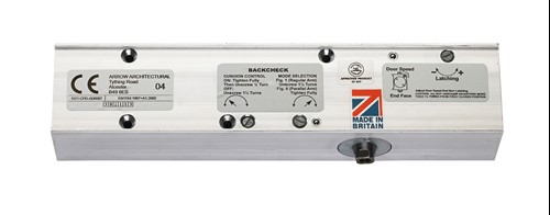
"Mode Selection" instructions and the adjustment valve itself are located on the front of the body of the door closer as shown below. Manual adjustment must be carried out via turning of the Mode Selection screw in order to adjust from Figure 1 to Figure 6.
The closer will be programmed as default in Figure 1 therefore no adjustment is required when fitting in this position. If however the closer is to be installed in Figure 6 (Push Side), the Mode Selection screw must be fully tightened in a clockwise direction.
Adjustment back to Figure 1 (if needed) can be achieved by turning the Mode Selection screw in a counter clockwise direction by 1 and a half turns as detailed on the body and/or fitting instructions.
If Mode Selection is not present on the body of your door closer then this model can only be installed in Figure 1 only. Units with Universal fitting include:
- Arrow 325
- Arrow 434
- Arrow 516
- Arrow Electromagnetic 600 Series
Why is the Door Slamming Shut?
If the closer is fitted to the provided template, then this will be down to two things:
- The door is too large/heavy and is overpowering the closer, or;
- The door closing speed and/or latch needs adjusting.
Details of how to correctly adjust the Speed or Latch can be found below or are detailed on the fitting instructions provided.
How to Adjust Closing Speed of a Door Closer
Speed Control adjustment can be located on the left end face of the body of a door closer (as shown in the image below), and can be used to control the closing speed of the door from its maximum opening angle to the closed position.
Fitting templates provided with the closer offer guidance on how to adjust the speed control appropriately but the key points of note are as follows:
- You should take care to ensure that only small adjustments are made to the closing speed of the closer at any one time.
- The door closing speed should be tested after each adjustment by fully opening the door and then allowing it to close.
- To ensure correct adjustment, we recommend adjusting the closer and testing its operation in conjunction with the use of a Force Meter gauge which will allow you to accurately adjust your opening and closing forces to ensure adherence to Building Regulations, the Equality Act and ADM.


How to Adjust Latching on a Door Closer
Latching adjustment controls how fast the door closes for the last few inches of the closing motion of a door.
It allows the door closing speed to be increased during the final degrees of movement to allow the door to fully close - overcoming and door seals and/or the latch plate in the process.
Arrow door closer latching comes in at approximately 7 degrees and can be adjusted via the latch valve located in the top right hand corner on the front of the closer body.
*Note - On doors with no latch, this valve can be screwed tight.

Once again, take care when adjusting the latching, make small adjustments each time and test the door after each adjustment to check functionality.
Implications of Over-Adjustment
As mentioned in the above sections, over adjustment of any of the valves can create problems for the installation and operation of your door closer.
When adjusting the door closer with the speed, latch or mode selection screw, make sure you do not unscrew the screw by more than 1 ½ turns from fully screwed in - Doing so will cause oil to leak from the body, and it will break the seal causing air to enter the body.
Why is the Electromagnetic Door Closer Arm Hitting the Top of the Door?
The arm of the door closer could be hitting the top of the door due to one of two reasons:
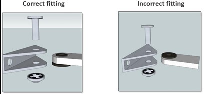
- Plastic Arm Bush
If fitted incorrectly as shown in the diagram below, the arm will drop by 2mm. This may cause the arm to hit the top of the door during operation and could also cause wear on the ear bracket and arm.
To avoid this,ensure the plastic arm bush is inserted correctly.
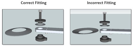
2. Dished Washer
If this is fitted incorrectly the arm will be loose and will catch on the top of the door during operation.
Ensure the Dished Washer is fitted as demonstrated below with the dome of the washer facing upwards.
How to Report a Problem
If you have been unable to resolve your issue by following the Installation Support above, you can contact our Technical Advisers who will be able to assist.
In order to get a fast resolution, we will require the following:
- The name/model of the closer
- The fitting position it is being installed in
- Several photos or a video of the door closer in question. The images/video should:
- Be taken whilst the closer is installed on the door
- Clearly show the body and arm
Support enquiries and images can be sent directly to [email protected].